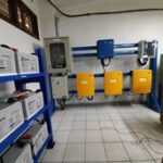
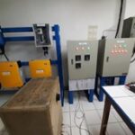
Microgrid Laboratory (eACCESS-MGL)
Supported by the Erasmus+ Programmed of the European Union: Capacity Building within the Field of Higher Education eACCESS Project number: 610041-EPP-1-2019-1-PL-EPPKA2-CBHE-JP
(EU-Asia Collaboration for accessible Education in Smart Power Systems)
Purpose
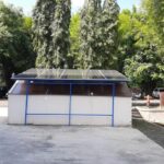
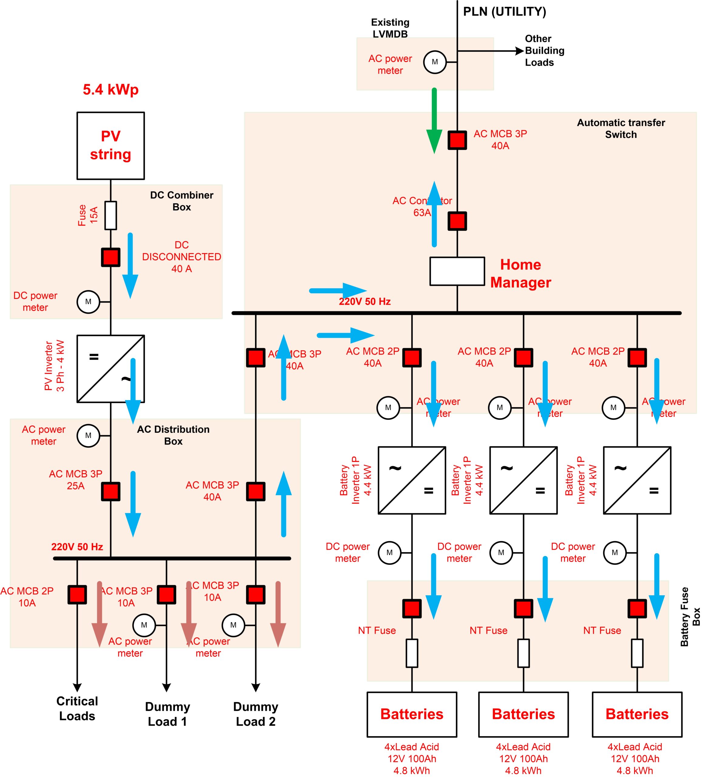
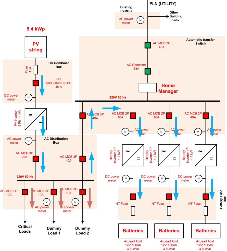
Soegijapranata Catholic University (SCU) eACCESS microgrid laboratory (eACCESS-MGL) was built for higher education and industrial workshops. This is a microgrid with 5,4 kWp PV arrays and 14,4 kWh batteries which are connected to utility (grid).
In the last one decade, the use of renewable energies has begun to grow rapidly. They are generally small in size and scattered. Similarly, wind power plants and photovoltaics have growth spready and are preferred because they are easy to built. The characteristic of such energies is intermittent. It means that they depend on availability of the sunlight or wind at a certain level. Therefore, the use of renewable energy must be integrated with utility.
Distributed Energy Resources (DER) including Distributed Generation (DG) and distributed storage (DS) are sources of energy located near local loads and can provide a variety of benefits including improved reliability if they are properly operated in the Electrical distribution system. Microgrids are systems that have at least one DER and associated loads, they can form intentional islands in the electrical distribution systems.
Equipment and description
PV MODULES
These PV Modules operate to produce electric energy from solar energy. The electric energy is in the form of DC quantity so in this application, a converter which can convert this DC voltage into AC voltage is required. SCU Microgrid Laboratory implements 10 x 540 Wp Photovoltaic Module (Monocrystalline type)
BATTERIES
The batteries are functioned as energy storage elements. When the system under islanding mode, the system relies on energy from the batteries and PV modules. The batteries can be charged by energy from utility or from PV-modules. 12 units of 12V 100 Ah Lead Acid Battery are installed in SCU Microgrid Laboratory as the energy storage elements.
PV INVERTER
This inverter has capability to convert the DC voltage as the output of PV modules into AC voltage which will be transferred into the busbar. The inverter must also be functioned as maximum power point tracker to maximize the PV output power. A 4 kW three-phase inverter is used in the SCU Microgrid Laboratory. This type of such an inverter is grid follower inverter, it will act as a controlled current source so its required voltage reference from grid or from grid former inverter.
BATTERY INVERTER
This inverter has capability to convert the DC voltage from the batteries into AC. Three single-phase inverters are use to operate in three phase system. These inverters can be operated as grid former inverter or grid follower inverter. When the microgrid is connected to the grid, the battery inverters operate as grid follower inverters. Meanwhile under islanding mode of operation, such inverters operate as grid former inverters.
HOME MANAGER
This will monitors all energy flows in the system, automatically identifies potential savings and facilitates efficient use of solar energy. Intelligent energy management is thus becoming even easier and more cost-effective
SCADA SYSTEM
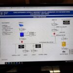
SCADA system must be capable to function for monitoring and controlling the system on different modes of operations. The quantities of voltages, currents, real power, reactive power, temperature and irradiation of the system must be able to be displayed on monitor graphically or in measurement numbers. Based on the measurements as the data, SCADA controls the status of the circuit breaker via the PLC.
Supervisory Control and Data Acquisition (SCADA) is a system of collecting information or data from the results of electricity measurements and then sending it to a central computer which will regulate, process, and control the data. The SCADA system is needed to handle a plant system by controlling, monitoring, marking, recording and retrieving data with a high level of complexity. The proposed SCADA system consists of a Master Terminal Unit (MTU), Human Machine Interface (HMI), Front End Processor (FEP), Data Communication Media, Remote Terminal Unit (RTU), and plants.
This SCADA system is formed by four components that have synergistic functions with each other, these components are:
- Transducer, instrumentation equipment in the form of sensors used to read analog or digital signals that are measured in the form of current, voltage, irradiance, temperature or other measurements
- Actuators (controlled contactors) are used to control equipment such as power flow connected to a PLC (RTU).
- Remote Terminal Unit (RTU), computer-based equipment that is placed at certain locations and places in the field. The RTU acts as a local data collector that gets its data from sensors and sends commands directly to the equipment in the field which functions to control the actuators and read signals from the sensors and communicate with the control center.
- The communication network is used to connect the RTU with the central station for MTU control, which can be a cable or radio network
- The Master Terminal Unit (MTU) is a computer that is used as a central processing unit for the SCADA system. This MTU provides a Human Machine Interface (HMI) for the user, and automatically adjusts the system according to the input from the sensor received.
Supervision and control functions in the SCADA system:
- Tele-signaling (TS) functions for sending signals to changes in state on the sensors that have been placed (current, voltage, irradiance, temperature). With this, it is expected that the real power, reactive power, power flow and irradiance conditions and temperature can be known in real time.
- Tele-control (TC) functions to operate the desired power flow and respond to what is desired
- Tele-metering (TM) which functions to read the desired data. The results of this monitoring are not only used as data loggers for the operation of the power flow, but can also be used in relation to remote control
One of the important things in a SCADA system is data communication between the remote system (remote station / RTU) and the control center. Communication on SCADA systems uses a special protocol, although there are also general protocols that are used. One of the protocols used in the SCADA system for electric power systems must comply with IEC Standards including IEC 60870-5-101 which is based on serial communication and IEC 60870-5-104 which is based on Ethernet communication.

Use/lab instructions
Realization of the microgrid system must be able to operate under different mode of operation, include mode of operation without battery and with battery. In laboratory practical implementation, some modes of operation will be conducted. These modes are:
- Grid connected without battery mode for PPV < PLoad
- Grid connected without battery mode for PPV > PLoad
- Grid connected with battery mode for PPV < PLoad
- Grid connected with battery mode for PPV > PLoad
- Islanding mode for PPV < PLoad
- Islanding mode for PPV > PLoad
GRID CONNECTED WITHOUT BATTERY MODE FOR PPV < PLoad
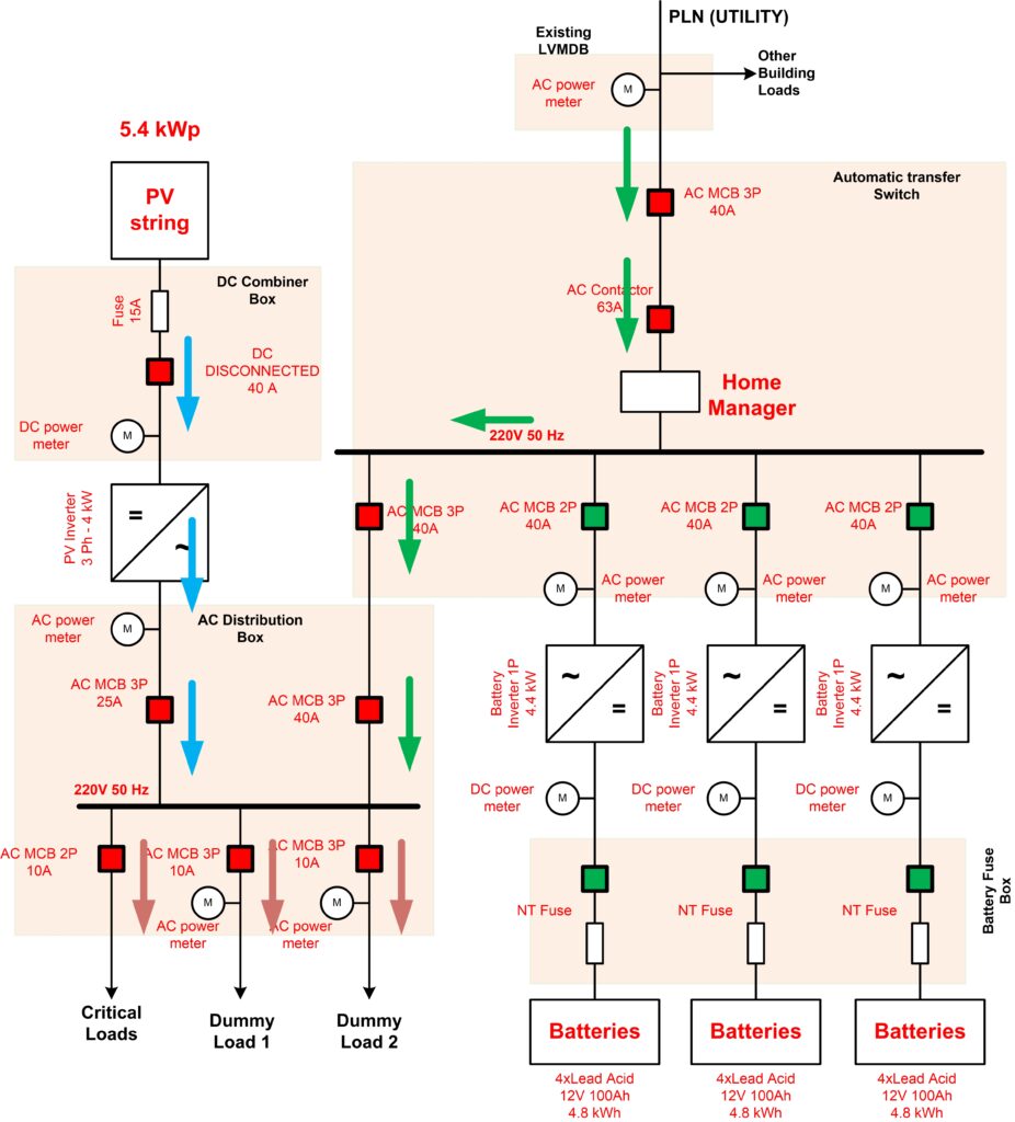
In mode the power absorbed by the loads is greater than the power generated by PV modules so it requires utility supply. PV-inverter will operate to convert DC voltage as output of PV modules into AC voltage and then transfer this power to the 220V 50Hz busbar. Another supply comes from the utility is also sent into 220V 50Hz as the PCC (point of common coupling) for the loads.
GRID CONNECTED WITHOUT BATTERY MODE FOR PPV > PLoad
In this mode, the power generated by the PV modules is greater than the power absorbed by the loads so part of the power from the PV modules is also sent to utility. The utility will receive power from the microgrid so this power can be used by other loads outside the microgrid. This condition can reduce the usage bill than must be paid to the utility company.
GRID CONNECTED WITH BATTERY MODE FOR PPV < PLoad
This mode uses the battery and the power absorbed by the loads is greater than the power generated by the PV modules. In this mode, all power from the PV modules must be transferred in to the loads, then the rest of power needed by the load can be supplied by the utility and the battery.
GRID CONNECTED WITH BATTERY MODE FOR PPV > PLoad
This mode uses the battery and the power absorbed by the loads is less than the power generated by the PV modules. In this mode, all power from the PV modules will be transferred in to the loads, then the rest of power will be supplied to the utility or to the battery.
ISLANDING MODE FOR PPV < PLoad
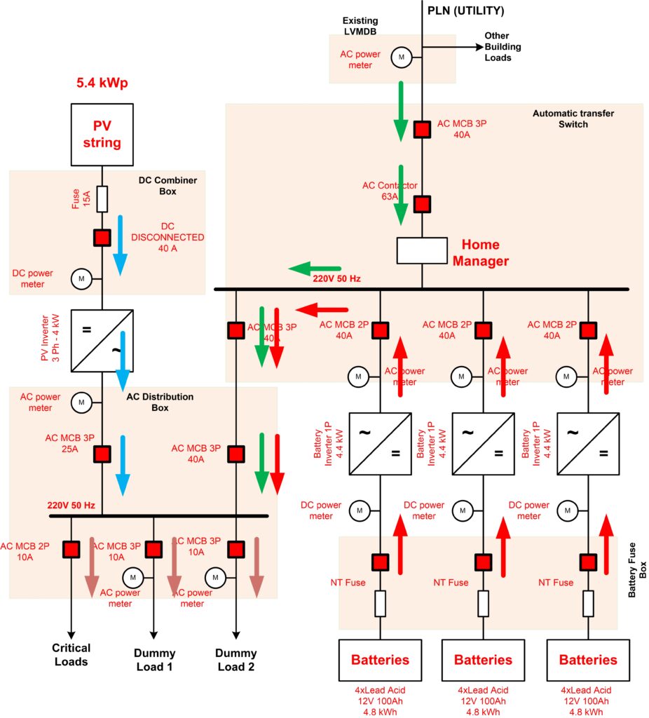
In this mode, the utility is disconnected from the microgrid so there are only two power sources: PV modules and the battery as energy storage. When the power absorbed by the loads is greater than the power generated by the PV modules, then the battery will supply the power to the loads through the battery inverter.
ISLANDING MODE FOR PPV > PLoad
In this mode, the power generated by the PV modules is greater than the power absorbed by the loads, so the rest of power can be sent to charge the battery. In this mode the battery converter


Contact information and Location

